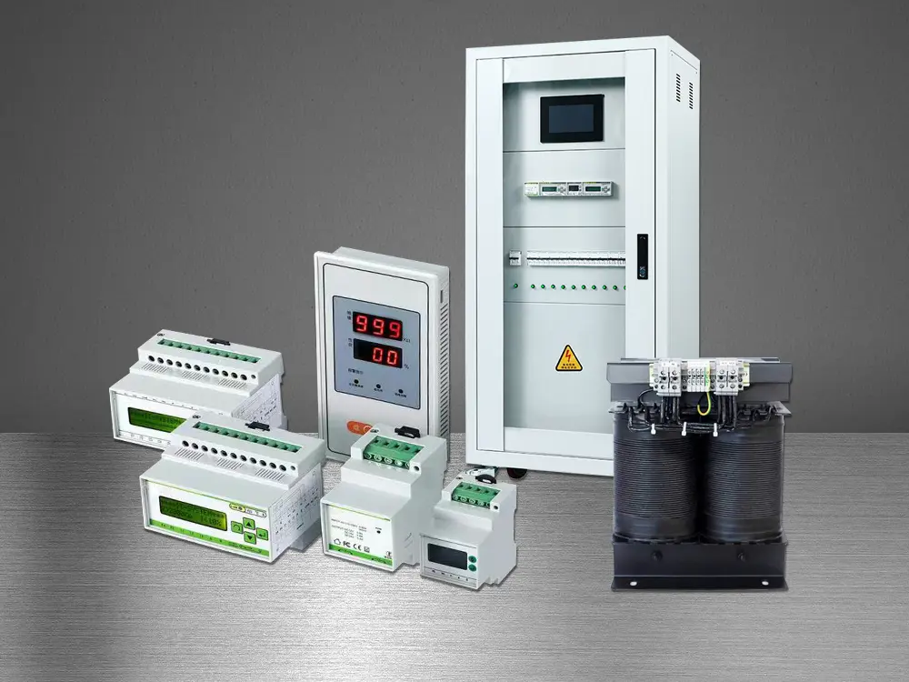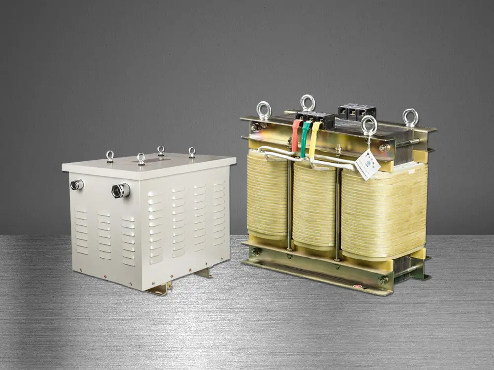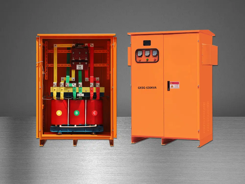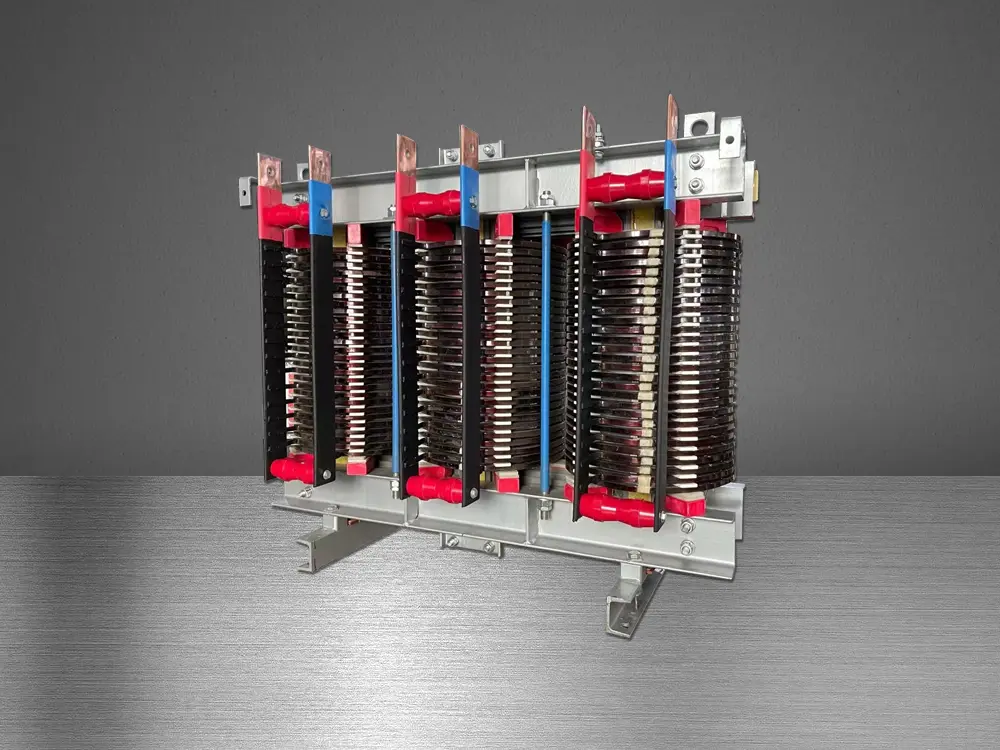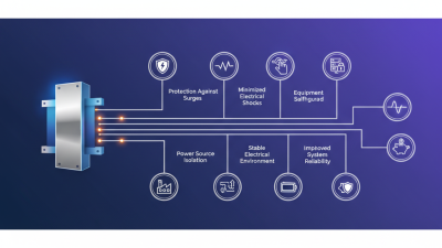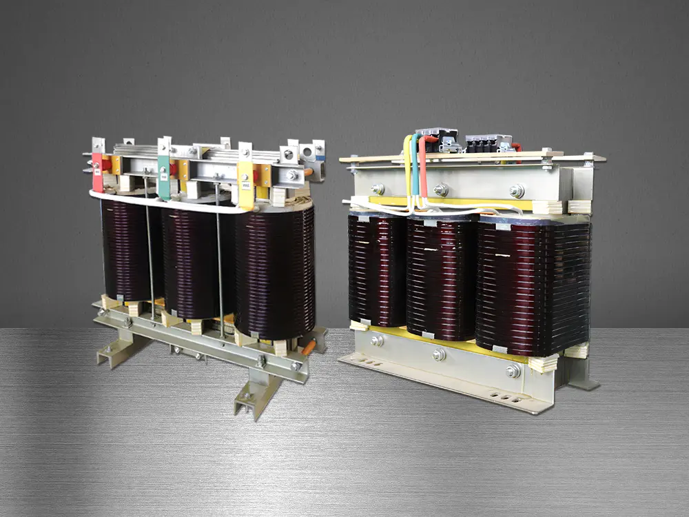
A Power Supply Isolation Transformer is more than a metal box between a utility line and sensitive equipment. It creates galvanic separation between the input and output circuits. This separation can reduce ground-loop currents, limit common-mode interference, and provide an additional safety barrier when correctly designed and installed.
The difference can be visible in practice. A control cabinet may stop producing a faint 60 Hz hum. A medical monitor may show a steadier waveform. An audio system may lose the buzz that appears when several devices share different grounding paths. These results are possible, not guaranteed. Transformer selection still matters.
Henry W. Ott, a respected EMC engineer and author, emphasized, “The best way to reduce common-mode noise is to eliminate the source.” His point remains relevant. A Power Supply Isolation Transformer cannot repair poor wiring, excessive load current, or a damaged grounding system. It should support a complete power-quality strategy, not replace one.
Engineers typically examine voltage rating, kVA capacity, insulation class, shielding, leakage current, and short-circuit performance. They also check inrush current. A transformer that looks adequate on paper may trip a breaker during energization. That detail is easy to miss.
There is no universal solution. An isolation transformer can add heat, weight, cost, and small voltage losses. It may also create a false sense of security. Proper installation, protective devices, testing, and maintenance remain essential. The real question is not whether isolation sounds beneficial. It is whether measured electrical problems justify the transformer’s limitations.
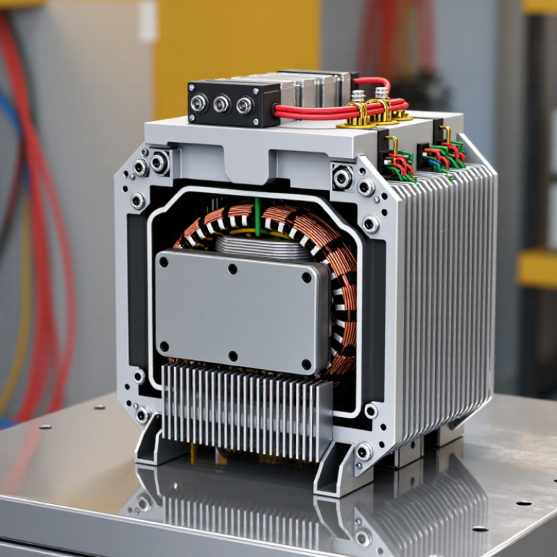
A power supply isolation transformer transfers electrical energy between two separate windings. The input winding connects to the source. The output winding feeds the equipment. There is no direct conductive path between them. This separation is called galvanic isolation.
The transformer uses magnetic induction instead of a shared electrical connection. Fault currents from the input side may therefore have fewer paths into sensitive circuits. This can improve safety during maintenance and reduce unwanted electrical noise. It is useful near test benches, control systems, medical equipment, and industrial power supplies. However, isolation does not make electricity harmless. The output can still deliver dangerous voltage and current.
An isolation transformer is not automatically a voltage stabilizer. It may also introduce small voltage losses and limited power capacity. Check its rated voltage, frequency, and load before installation. A protective earth may still be necessary, depending on the equipment and local electrical rules. Never assume that an isolated output needs no grounding.
The transformer should have suitable fuses, enclosure protection, and ventilation. Measure the output under actual load, not only at idle. In practice, designers sometimes expect isolation to solve every power problem. That assumption needs review. Noise, surges, poor wiring, and overloads may require separate solutions.
Why Use a Power Supply Isolation Transformer?
Electrical isolation works by separating the input and output circuits through magnetic coupling. The primary winding receives AC power. Its changing magnetic field induces voltage in the secondary winding. There is no direct conductive path between them. This break can reduce shock risk, interrupt ground-loop currents, and limit some noise travelling through protective earth. IEC 61558-1 specifies safety requirements for power transformers, including insulation systems and dielectric testing. The Uptime Institute’s 2024 Global Data Center Survey reported that 54% of respondents experienced an outage costing less than $100,000, while major incidents exceeded $1 million for many operators. Isolation cannot prevent every failure. It is one layer, not a magic shield.
Tips: Select the transformer from the load’s voltage, frequency, VA rating, and inrush current. Check creepage and clearance distances. Bonding the secondary neutral requires careful design. A floating output may confuse protection devices. During commissioning, measure insulation resistance and verify fault-current paths. Electrical workers should follow IEC 61557 test practices and local safety rules. Keep metal enclosures grounded. Label both sides clearly.
In industrial panels, isolation transformers can help sensitive instruments survive upstream disturbances. They also make troubleshooting quieter because unwanted circulating currents have fewer paths. However, poor grounding can create new hazards. I have seen designs focus on isolation while ignoring overload protection. That is an expensive oversight. Review the complete protection scheme, not only the transformer nameplate.
| Technical Dimension | Typical Characteristic or Value | How It Supports Electrical Isolation |
|---|---|---|
| Electrical Connection | No direct conductive connection between primary and secondary windings | Energy is transferred magnetically through the transformer core, creating galvanic separation between the input circuit and the isolated output circuit. |
| Operating Principle | Alternating current creates a changing magnetic flux in the core | The changing magnetic field induces a voltage in the secondary winding without requiring a shared electrical conductor. |
| Common Voltage Ratio | 1:1 for isolation transformers; other ratios are available | A 1:1 design provides isolation while keeping the nominal output voltage close to the input voltage. Non-unity ratios can also step voltage up or down. |
| Typical Frequency | 50 or 60 Hz for utility-frequency power systems | The transformer must be designed for the intended frequency. Lower frequencies generally require a larger magnetic core for the same power rating. |
| Dielectric Withstand | Often tested in the kilovolt range, according to the applicable safety standard and product design | Insulation between windings is tested to verify that it can withstand a specified transient or test voltage without electrical breakdown. |
| Insulation Resistance | Normally specified in megohms or higher when measured under a defined test condition | High resistance limits leakage current through the insulation system and helps maintain separation between primary and secondary circuits. |
| Leakage Current | Depends on winding capacitance, shielding, insulation, load, and applicable safety limits | Low leakage current reduces unintended current paths to earth or between isolated circuits. The permitted value must be evaluated against the relevant safety requirements. |
| Common-Mode Noise | Attenuation depends on construction; electrostatic shielding can improve high-frequency noise rejection | Isolation interrupts many ground-related noise paths. A shield connected as specified by the design can reduce capacitive coupling between windings. |
| Ground-Loop Prevention | The isolated secondary can be grounded at one deliberate point or left floating, subject to the system design | Because the secondary is not directly bonded to the primary, unwanted circulating currents caused by multiple grounding points can be reduced. |
| Safety Benefit | The secondary is separated from the supply conductors, but it is not automatically touch-safe | Isolation can reduce shock risk in suitable applications, yet exposed secondary conductors may still be hazardous. Fusing, enclosure, grounding, and protective measures remain necessary. |
| Efficiency | Common power transformers are often approximately 90% to 98% efficient, depending on size and load | The transformer introduces copper loss, core loss, and leakage-related losses. Larger units often achieve higher efficiency near their intended operating load. |
| Voltage Regulation | The output voltage can decrease as the load increases; the amount depends on transformer impedance | Winding resistance and leakage reactance cause a difference between no-load and full-load voltage, so sensitive equipment may require additional regulation. |
| Load Compatibility | Rated in volt-amperes (VA) or kilovolt-amperes (kVA) | The connected load should remain within the rated apparent power and inrush capability. Motors, capacitive-input supplies, and other nonlinear loads may require extra capacity. |
| Inrush Current | A short-duration current that can be several times the steady-state magnetizing current | Inrush occurs when the core is energized and may trip an undersized protective device. Circuit protection should account for the transformer’s startup behavior. |
| Galvanic Isolation Limitation | Isolation does not block magnetic coupling, capacitive coupling, or electromagnetic interference by itself | A transformer removes the direct conductive path, but high-frequency noise and transients can still cross through parasitic capacitance or connected equipment. |
| Typical Applications | Test benches, medical equipment subsystems, control circuits, instrumentation, and noise-sensitive systems | These applications benefit from separated reference potentials, reduced ground-loop currents, improved measurement safety, or controlled power distribution. |
| Main Trade-Offs | Added size, weight, cost, heat generation, and voltage drop | Isolation improves circuit separation but does not replace a complete protection design. Selection should consider power rating, insulation system, regulation, thermal performance, and installation requirements. |
A power supply isolation transformer can reduce shock risk by separating a device from the building’s grounded supply. Its secondary winding is electrically isolated from the primary. If a worker touches one secondary conductor while standing on a grounded floor, the fault current may remain limited. The danger is lower, not absent. Touching both conductors can still be fatal.
The need is serious. The U.S. Bureau of Labor Statistics recorded 145 occupational deaths from exposure to electricity in 2022. Isolation transformers cannot prevent every electrical injury, but they can reduce some single-fault shock paths. This matters near test benches, medical equipment, and damp industrial areas. A metal tool dropped across exposed terminals can still create an arc, heat, or fire. The transformer does not replace guarding, insulation, grounding, overcurrent protection, or lockout procedures.
NFPA 70E stresses risk assessment, boundaries, and energized-work controls. IEC 61558-2-4 also addresses safety requirements for separating transformers. In practice, technicians should verify the transformer’s rating, enclosure, insulation, and secondary grounding design before connection. A floating output may look reassuring on a meter. It can still hold dangerous voltage under fault conditions. That is the uncomfortable point: isolation lowers one pathway, not the whole hazard. Controls are often treated as automatic, and that assumption deserves review.
Power supply isolation transformers are commonly used where electrical noise, ground loops, or shock risks require better control. They separate the input circuit from the output circuit through magnetic coupling. This arrangement can limit unwanted current paths. It can also protect sensitive equipment from disturbances on the main supply. However, isolation alone does not make a system safe. Proper grounding, fuses, insulation, and testing remain essential.
Hospitals use isolation transformers in selected patient-care areas, where leakage current requires careful management. Laboratories use them for test benches, instruments, and measurement equipment.
Industrial control panels may include isolation transformers to reduce interference from motors and switching devices. They also appear on construction sites, service benches, and audio systems affected by ground-loop hum.
In practice, the correct rating matters greatly. A poorly sized transformer may overheat, create voltage drops, or fail during startup. Isolation reduces one risk, but it can introduce another if users misunderstand the separated output.
Tips: Check the transformer’s voltage, power rating, frequency, and enclosure before installation. Leave space for cooling. Test the system under realistic loads, not only at idle. Ask a qualified electrician to verify grounding and protective devices. I have seen small details, such as loose terminals, undermine an otherwise careful installation.
Why Use a Power Supply Isolation Transformer?
Choosing an isolation transformer requires more than matching input and output voltage. The first question is the load’s real demand. A 500 VA device may draw higher current during startup, especially with motors, capacitors, or switching supplies. Leave practical headroom.
Check the required voltage, frequency, and continuous load rating. Isolation alone does not guarantee voltage regulation. If sensitive instruments are connected, regulation and noise performance matter. Insulation class, dielectric strength, and grounding arrangements also deserve careful review. In a dusty workshop, a protected enclosure can prevent trouble. In a warm cabinet, cooling becomes important. Heat shortens service life.
Tips: Record the equipment’s running current and startup behavior. Select a transformer with suitable VA capacity, not just the average wattage. Confirm compatibility with the local electrical system and installation rules. Ask a qualified professional to verify protection, earthing, and clearances.
There is also a practical detail people often miss: physical size and sound. A transformer that fits on paper may crowd the cabinet or hum beside a measurement sensor. I have seen installations fail because the enclosure became too hot, not because the transformer was electrically undersized. Recheck the assumptions. Loads change over time. A slightly higher capacity may improve reliability, but excessive oversizing can increase cost and idle losses.
Isolation transformers provide galvanic separation between the source and the load, helping reduce shock hazards, interrupt ground-current paths, and limit the transfer of common-mode electrical noise. The transformer rating must be selected according to load power and operating conditions.
The chart uses the single-phase relationship I = S ÷ V, where S is apparent power in volt-amperes and V is voltage. At 230 V, a 1 kVA transformer supplies approximately 4.35 A at full load. When choosing a transformer, also verify the input and output voltage, frequency, load inrush current, insulation system, cooling method, allowable temperature rise, and required safety certifications. A suitable rating should provide operating headroom rather than running continuously at its maximum capacity.