Choosing a High Tension Current Transformer is not just a matter of matching a voltage rating. Buyers must consider primary current, insulation level, accuracy class, burden, installation conditions, and protection requirements. A unit that looks suitable on a datasheet may not fit the actual switchgear or measurement circuit. Small details matter.
The International Energy Agency’s Electricity Grids and Secure Energy Transitions report (2023) estimates that annual grid investment needs to rise to more than USD 600 billion by 2030. That expansion places greater attention on dependable measurement and protection equipment. Current transformers support both by scaling high primary currents into values that meters and relays can use. IEC 61869-2 sets requirements for inductive current transformers, offering buyers a useful standards reference. Still, compliance alone does not prove that a model suits every site.
This guide compares ten options through practical purchasing criteria, including rated current, accuracy, insulation design, and application fit. Look closely at nameplate data and manufacturer documentation. Ask how the transformer performs under your expected load and fault conditions. Not every listing provides equally clear test information. That is worth questioning. The “best” choice depends on the network, not a single ranking. A careful comparison can help narrow the field, but final selection should be checked against project specifications by a qualified power-system professional.
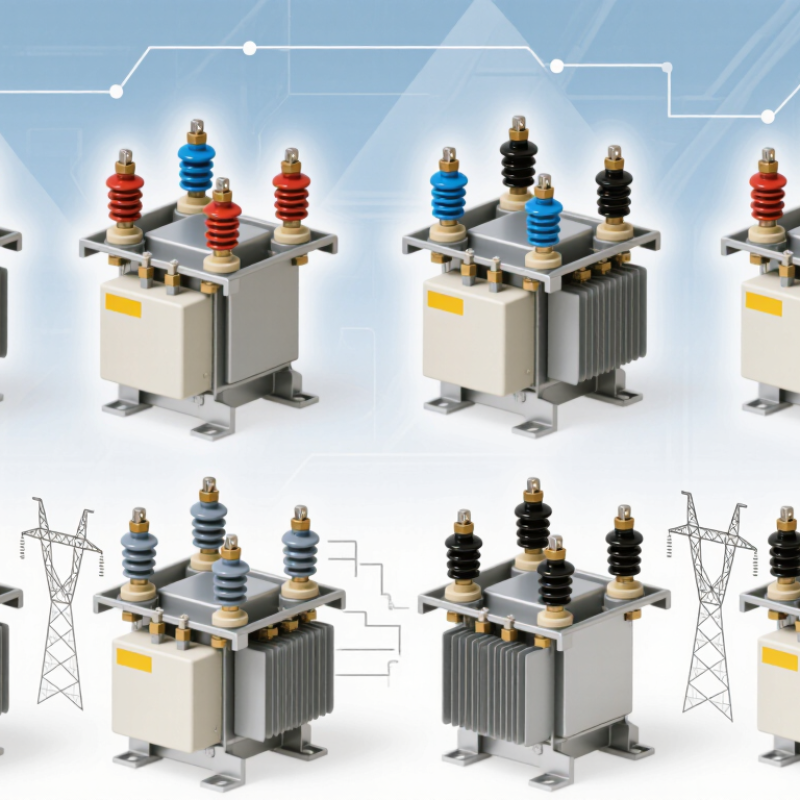
Screen 10 High-Tension CTs by Rated Voltage, Insulation, and Mounting
A useful comparison starts with the system’s maximum operating voltage, not a catalog ranking. Screen all ten candidates against the network voltage and required insulation levels. Check power-frequency and impulse withstand ratings. A CT that matches nominal voltage may still lack suitable margin for switching surges or site conditions. Small detail, big consequence. Verify the nameplate and test documents rather than relying on a product summary.
Insulation must suit the installation. Porcelain or composite housings face rain, dust, salt, and ultraviolet exposure. Internal oil, gas, and resin systems have different monitoring and maintenance needs. Review creepage distance, clearances, seals, and temperature limits. Ask how routine and partial-discharge tests are documented. These checks are easy to overlook. A compact design can look appealing until the site’s pollution level is considered; I would revisit that judgment before choosing.
Mounting can quickly narrow the shortlist. Post-mounted CTs need stable supports and workable lead access. Bushing designs fit around existing equipment, but depend on precise interface dimensions. GIS or tank-mounted units require compatible enclosure layouts. Confirm phase spacing, terminal orientation, lifting points, and service clearance from drawings. A neat photograph is not enough. Record voltage class, insulation type, mounting footprint, and test evidence in one table. Then check ratio, accuracy, and burden against the intended relay or meter. One field measurement may still surprise you.

When comparing high-tension current transformers, treat the metering class as a load-dependent accuracy rating, not a blanket guarantee. IEC 61869-2:2012 specifies current-error limits at defined operating points. Between 100% and 120% of rated current, the limits are ±0.1% for class 0.1, ±0.2% for 0.2, ±0.5% for 0.5, and ±1.0% for 1.0. At 5% rated current, the respective limits widen to ±0.4%, ±0.75%, ±1.5%, and ±3.0%. Low-load performance can matter. A transformer that looks precise at full load may not be as precise overnight.
For high-value revenue metering, classes 0.1 or 0.2 may suit the measurement target; class 0.5 or 1.0 may be adequate for less demanding monitoring. Confirm the required class against local metering rules and the actual operating range. Also check rated burden, cable length, and connected meter load: these affect whether the installation matches the conditions used for accuracy testing. A tidy specification can still mislead. For example, a lightly loaded CT with long secondary wiring may behave differently from the test setup. IEC class figures are useful comparison data, but they do not replace checking the complete measurement circuit.
Choosing a protection current transformer starts with the relay’s requirements, not the lowest price. A 5P or 10P class describes the permitted composite error at the stated accuracy limit factor and rated burden. For example, a 5P10 CT is specified for no more than 5% composite error at ten times rated current, under its rated burden conditions. Details matter.
Rated burden is expressed in VA and includes the connected relay, meters, and secondary wiring. Long cable runs can add meaningful burden, especially with smaller secondary conductors. Measure both runs. Compare the calculated total with the CT’s rated burden, then check the accuracy limit factor against the maximum fault current your protection scheme must detect. A CT that meets its class on paper may saturate sooner if the actual burden is higher.
For a 5P or 10P selection, use the protection study and relay data together. A 5P class generally allows less error than 10P at the stated limit, but it is not automatically the right choice for every installation. Confirm rated primary and secondary currents, burden in VA, and the required limit factor from the equipment documentation. One detail is easy to miss: wiring resistance changes with conductor length and temperature. Catalog assumptions may not match the panel. Inspect the installation and verify the figures before ordering.
For high-tension current transformers, the secondary rating must match the relay or meter input. IEC 61869-2:2012 recognizes 1 A and 5 A rated secondary currents, while IEEE C57.13-2016 provides related requirements for current-transformer ratings, accuracy, and burden. Check the device nameplate and technical manual; matching the number alone is not enough. The CT ratio and rated burden must also suit the connected circuit.
Cable length can influence the choice. At equal loop resistance, a 5 A secondary produces 25 times the wiring loss of a 1 A secondary, since losses rise with current squared. That can make 1 A practical for long runs between a switchgear panel and a control room. Still, it is not automatically the right option: existing relays may require 5 A inputs. Check the nameplate. In retrofit work, old drawings may not reflect the installed equipment, so verify the actual input rating and wiring. Never leave an energized CT secondary open; follow the manufacturer’s specified shorting and maintenance procedure.
At the same secondary-circuit resistance, a 5 A output produces 25 times the resistive loss of a 1 A output, based on P = I²R. Values shown are calculations for the stated resistances, not product ratings. Check the transformer’s rated burden and confirm that its secondary output matches the relay or meter input.
When comparing high-tension current transformers, check Ith and Idyn against the fault conditions at the actual installation point. Ith is the rated short-time thermal current, usually expressed as an RMS value for a stated duration. Idyn is the peak current the transformer can withstand mechanically. They are not interchangeable. A high Ith figure alone does not prove that windings and supports can tolerate the first fault-current peak.
Check the duration. Compare Ith with the expected fault current and the protection system’s clearing time. For Idyn, consider the peak asymmetry that can occur during a fault, which depends partly on the system’s X/R ratio.
Numbers need context. IEEE C57.13 compliance is useful, but confirm the applicable edition, test documentation, and project requirements rather than relying on a brief catalog claim. A tidy rating table can still hide a mismatch.
I would also check that the specified ratings apply to the selected ratio and construction, and that installation conditions do not reduce the stated limits. If the fault study is incomplete, pause before selecting a unit; an assumed clearing time can make an otherwise reasonable comparison misleading.