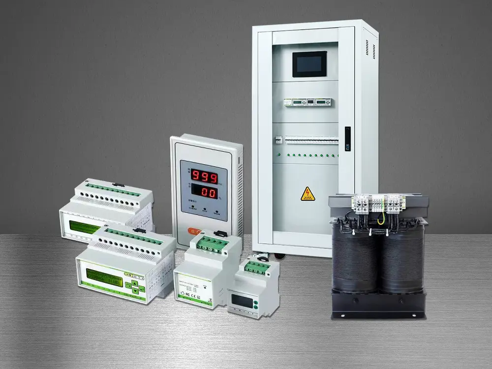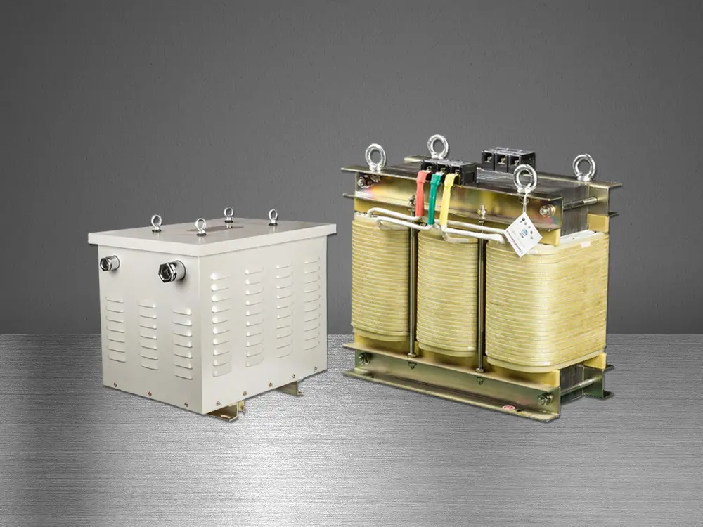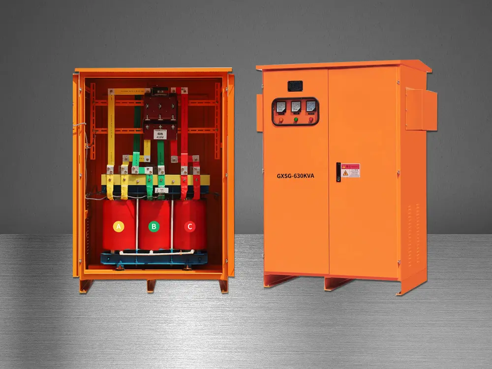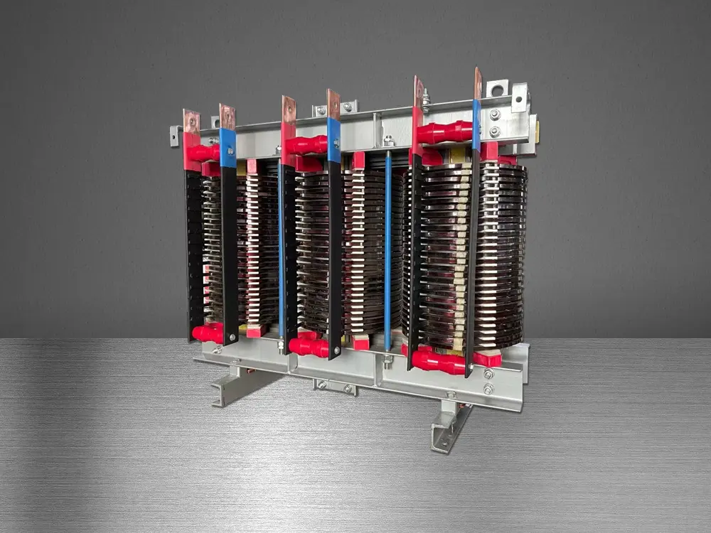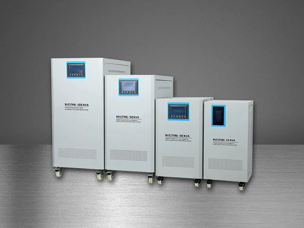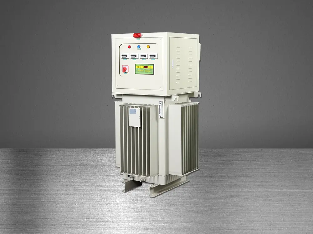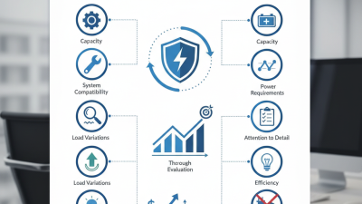
Choosing the best Automatic Voltage Stabiliser in 2026 requires more than comparing prices, capacity, or cabinet size. Modern facilities face unstable utility supplies, sensitive electronics, motor starting currents, and uneven phase loads. A voltage stabiliser must respond quickly without creating new problems. That means checking correction speed, output accuracy, surge tolerance, thermal performance, bypass design, and maintenance access.
The International Energy Agency’s Electricity 2024 report forecasts global electricity demand to grow by an average of 3.4% annually from 2024 to 2026. More demand also means greater pressure on ageing distribution networks. Mordor Intelligence’s Voltage Stabilizer Market analysis highlights industrial, commercial, and residential applications as important demand segments. However, market forecasts are not equipment recommendations. They often combine different stabiliser technologies and regional conditions. That limitation deserves attention.
Power-quality engineer Roger C. Dugan offers a useful starting point: “Power quality is any power problem manifested in voltage, current, or frequency deviations that results in failure or misoperation of customer equipment.” His definition explains why the largest unit is not always the best choice. A factory may need a three-phase servo stabiliser, while a clinic may need precise regulation for imaging equipment. A small office may only require basic relay correction.
Look closely at the real load. Measure voltage at different hours. Check neutral balance, harmonics, and generator compatibility. IEC 60038 and IEC 61000 provide useful reference points, but local installation conditions still matter. The best Automatic Voltage Stabiliser is therefore the one that matches measured voltage behaviour, connected equipment, safety requirements, and realistic maintenance capability.
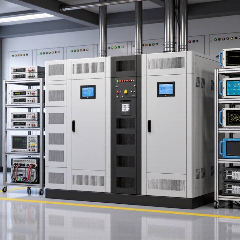
The answer starts with the supply voltage, not the product label. EN 50160 describes voltage characteristics on public low-voltage networks. For a nominal 230 V supply, the usual ±10% range means approximately 207 to 253 V under normal conditions. That range is a useful reference for homes, offices, workshops, and small commercial sites.
It is not a promise that every second will remain inside those limits. Short disturbances, switching events, and local network faults can still occur. A reliable assessment should record voltage at different times, especially when pumps, heaters, or compressors start. A simple meter reading at midday may hide the real problem. I have seen installation decisions based on one reading, and that is rarely enough.
The best automatic stabiliser should match the measured input range, connected load, and equipment sensitivity. Check continuous capacity, starting current, correction speed, output accuracy, thermal protection, and bypass operation. A unit designed for 207–253 V may be unsuitable where the supply regularly falls below 180 V. Capacity also matters: a motor marked 3 kW can demand much more during startup. Quiet operation helps in offices, while clear alarms and accessible maintenance points matter in workshops. Do not oversize blindly. Excess capacity can increase cost without improving regulation, and even careful specifications cannot replace a proper site survey.
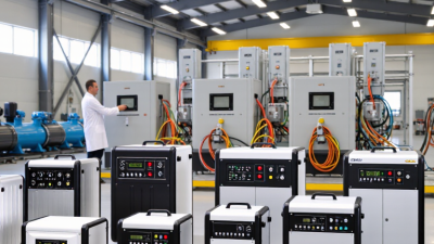
Choosing the best automatic voltage stabiliser in 2026 depends on response speed, accuracy, and load behavior. Relay AVRs switch between fixed voltage steps. They are affordable and simple, but their correction is relatively coarse. A lamp may visibly brighten or dim during switching. Sensitive equipment can also notice short transition gaps.
Servo AVRs use a motor-driven transformer to adjust voltage gradually. They usually provide better accuracy than relay designs, often keeping output within a narrow tolerance under changing loads. However, the motor needs time to move. A sudden drop from 230 volts to 180 volts may not be corrected instantly. Moving parts also require inspection after years of service. Quiet operation is not guaranteed.
Static AVRs use power electronics rather than mechanical contacts or motors. Their response can be extremely fast, often handling sharp fluctuations within milliseconds. They suit control systems, medical support equipment, and precision instruments when carefully specified. Their accuracy is strong, but heat management and waveform quality matter. A poorly cooled unit may lose performance under continuous load. That detail is easy to miss.
In practical testing, relay models work well for heaters, lighting, and basic appliances with broad voltage tolerance. Servo systems fit workshops and offices where steady correction matters more than instant reaction. Static designs offer the strongest protection for sensitive loads, but usually cost more. The “best” choice is not always the most accurate one. Measure starting current, voltage range, ambient temperature, and required output tolerance before selecting a stabiliser. Otherwise, a technically impressive unit may still be the wrong fit.
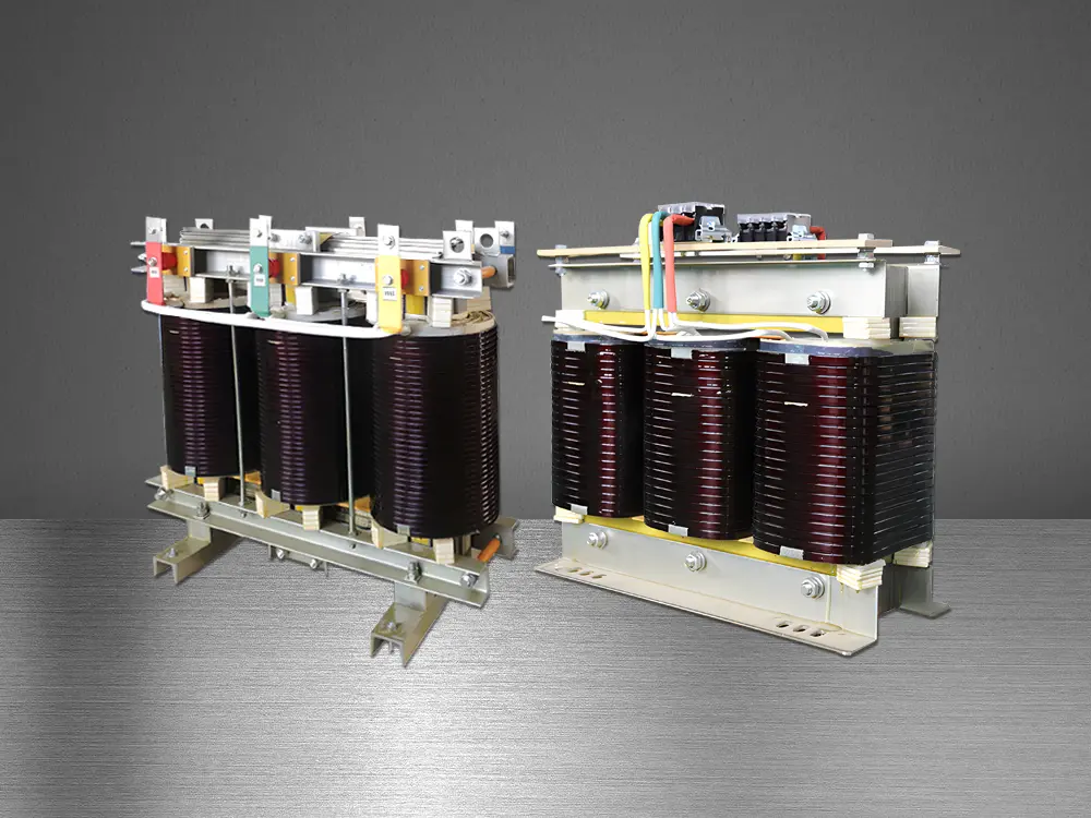
In 2026, the best automatic voltage stabiliser is not chosen by price or a product label. It is sized from measured apparent power and transformer duty. IEC 60076-1 defines transformer ratings in kVA or MVA under specified service conditions, not simply connected wattage. This distinction matters. A 100 kW load at 0.8 power factor already demands 125 kVA before motor starting or future expansion.
Calculate S = P / PF, then check the lowest input voltage and phase current. For a three-phase stabiliser, current is I = 1,000S/(√3V).
If the measured load is 125 kVA, a practical engineering allowance of 20–30% gives 150–163 kVA. Select the next available rating. Verify continuous thermal duty.
IEC 60076-1 does not automatically confirm a stabiliser’s overload capability. That assumption is risky.
Large inrush can dominate sizing. Motors, compressors, and transformers may briefly exceed running kVA, so record starting current with a power-quality analyser. The IEA Electricity 2024 report forecasts global electricity demand to grow by an average 3.4% annually through 2026.
Capacity planning matters more than guesswork. The U.S. Department of Energy’s 2016 distribution-transformer technical report treats load factor and peak demand as separate design inputs.
Field readings are imperfect. A neat spreadsheet can still miss a 30% voltage sag. Check neutral loading, harmonics, ambient temperature, and bypass operation before approval.
Choosing the best automatic voltage stabiliser in 2026 requires more than checking its correction range. Surge protection deserves equal attention, especially where motors, long cables, or unstable grids are present.
IEC 61000-4-5 evaluates immunity to simulated surges, including short high-energy pulses from switching and lightning effects. It does not certify that an AVR can absorb every field surge. A practical unit should combine metal-oxide varistors, thermal disconnects, input fuses, and clearly specified clamping voltage. Some designs also add gas discharge tubes or transient voltage suppressors for layered protection.
Overvoltage protection should disconnect the load when the input remains dangerously high. Look for adjustable limits, fast isolation, automatic restart delay, and visible fault indication. Under-voltage protection matters too, because low voltage can overheat compressors and motors. Grounding and cable routing still influence the result. No AVR can compensate for poor earthing.
In site testing, I would record input voltage, output stability, surge indicators, and recovery time under realistic loads. A glossy datasheet is not enough. Real installations are messier. I would not treat every IEC reference as proof of complete protection, because test conditions may differ from the installation. Select a stabiliser with verified surge coordination, appropriate energy ratings, and protection matched to the connected equipment.
How to interpret the chart: IEC 61000-4-5 defines combination-wave surge immunity test levels from 0.5 kV to 4 kV open-circuit voltage. A capable automatic voltage stabiliser should combine voltage regulation with overvoltage and undervoltage cut-off, surge protection, thermal protection, short-circuit protection, and a safe bypass or shutdown function.
Important: AVR regulation corrects sustained voltage variation, but it does not replace a properly coordinated surge protective device. The selected AVR and SPD should be matched to the installation category, wiring system, grounding arrangement, and required IEC test level.
What Is the Best Automatic Voltage Stabiliser in 2026?
How Can 2026 Buyers Match ±1% Regulation to Load and Grid Conditions?
A ±1% specification sounds ideal, but it only matters when matched to real operating conditions. Measure first. Record incoming voltage across several days, including evening peaks and generator changes. A stabiliser should handle the lowest and highest readings without reaching its correction limit. Otherwise, precise regulation becomes a paper promise.
Load behaviour matters just as much. Motors, compressors, welders, and medical equipment can draw sharp starting currents. Select capacity using running load, starting surge, power factor, and future expansion. A practical margin of 20–30% can prevent overheating, but excessive oversizing may reduce efficiency and raise costs. For sensitive electronics, check response time, output waveform, and bypass protection. ±1% regulation is useful, yet a slow unit may still expose equipment to brief disturbances.
I once focused too heavily on the headline accuracy and underestimated a workshop compressor’s starting surge. The stabiliser performed well during normal operation, but its protection tripped during repeated starts. That experience changed my checklist. Buyers should request test conditions, correction speed, overload behaviour, and phase requirements. They should also confirm whether the stated ±1% applies across the full input range or only near nominal voltage. Installation quality remains important. Loose terminals, undersized cables, poor ventilation, and weak earthing can undermine an otherwise capable unit. A qualified technician should verify these details before commissioning.
| Load and Grid Condition | Recommended Stabiliser Type | Typical Input Range | Output Regulation | Typical Response Time | Suitable Load Profile | Sizing Guidance | Main Trade-Off |
|---|---|---|---|---|---|---|---|
| Stable grid with occasional moderate voltage variation | Servo-controlled automatic voltage stabiliser | Approximately 180–250 V for a 230 V system | Up to ±1% when correctly specified and calibrated | Typically 0.5–1.5 seconds | General commercial equipment, lighting, control panels and non-critical machinery | Usually select 20–30% above the calculated continuous apparent power | Mechanical wear from the motor and variable transformer; slower than static designs |
| Frequent voltage fluctuations with sensitive electronic equipment | Static electronic voltage stabiliser | Commonly 160–260 V, depending on the design | Typically ±1% or better under rated conditions | Approximately 1–10 milliseconds | Servers, laboratory instruments, automation systems and precision electronics | Allow extra capacity for inrush current and harmonic-producing loads | Higher purchase cost and possible heat dissipation requirements |
| Wide or prolonged undervoltage on a weak rural or industrial feeder | Wide-input servo or static stabiliser with low-voltage protection | Often 140–260 V, subject to the rated correction range | ±1% only while the input remains inside the correction window | Approximately 10 milliseconds to 2 seconds, depending on technology | Industrial controls, pumps, workshops and mixed commercial loads | Check that the stabiliser does not bypass or shut down below its minimum input voltage | Maximum output power may decrease when input voltage is very low |
| Rapid sags, swells or electrically noisy supply | Static stabiliser combined with surge protection and power conditioning | Typically 170–250 V for a 230 V system | About ±1% in the specified operating range | Usually below 10 milliseconds | Medical electronics, measurement systems, networking equipment and PLCs | Use a separate surge protective device and verify short-circuit withstand rating | Does not replace a UPS during a complete power interruption |
| Large motor, compressor or transformer loads | Heavy-duty servo stabiliser or static stabiliser rated for motor starting | Approximately 170–250 V, depending on the feeder | Usually ±1% at steady state; temporary deviation may occur during starting | Typically 0.5 seconds to several seconds for servo systems | Motors, refrigeration compressors, pumps and workshop machinery | Account for locked-rotor current, commonly several times the motor's running current | Starting current can trigger overload protection if the unit is undersized |
| High-load three-phase commercial or industrial installation | Three-phase automatic stabiliser with phase monitoring | Commonly 320–460 V line-to-line for a 400 V system | Typically ±1% line-to-line when phase balance is within specification | Approximately 0.5–3 seconds for servo designs | Production lines, lifts, HVAC systems and three-phase distribution boards | Check phase sequence, phase imbalance, neutral requirements and per-phase loading | More complex installation and greater sensitivity to unbalanced loads |
| Small office or home load with moderate voltage instability | Single-phase automatic stabiliser with bypass and delay protection | Typically 180–250 V for a 230 V system | ±1–3%, depending on the selected unit and load | Approximately 0.5–2 seconds | Computers, televisions, small appliances and office equipment | Include the combined running load and the largest appliance's starting demand | A ±1% specification may be unnecessary for ordinary resistive appliances |
| Equipment requiring uninterrupted operation | Online UPS with voltage regulation, optionally preceded by a stabiliser | Depends on the UPS input window; commonly wider than 160–280 V | Often ±1% at the UPS output | Near-zero transfer interruption for online topology | IT systems, telecoms, laboratory equipment and critical control systems | Size by watts, VA, battery runtime and crest-factor requirements | Higher cost, battery maintenance and conversion losses |
| High ambient temperature, dust or limited ventilation | Industrial-rated stabiliser with thermal derating and forced ventilation | Use the manufacturer's derated operating range | ±1% only if temperature and load remain within rated limits | Technology-dependent | Factories, plant rooms, outdoor cabinets and dusty locations | Prefer a continuous rating with at least 20–30% spare capacity after derating | Fans, filters and airflow paths require scheduled maintenance |
| Grid with frequent complete outages | Stabiliser plus generator or UPS; a stabiliser alone is insufficient | Must match the generator or utility voltage range | ±1% during regulation, not during an outage | Depends on the backup source and transfer system | Any load requiring continuity during loss of mains power | Coordinate voltage, frequency, transfer time and generator step-load capability | More equipment, installation space and maintenance are required |
| Reference calculation at 230 V and power factor 0.90 | Use apparent power, not only real power, for selection | Formula: current ≈ VA ÷ 230 | Output target: 230 V ±1% = approximately 227.7–232.3 V | Response must be matched to the load's sensitivity | Continuous load, starting load and non-linear load should be evaluated separately | 5 kVA ≈ 12.1 A; 10 kVA ≈ 24.2 A; 20 kVA ≈ 48.3 A; 30 kVA ≈ 72.5 A | Actual current varies with voltage, phase configuration and power factor |
| Buyer verification before selecting a ±1% model | Compare measured site data with the complete technical specification | Record minimum, maximum and average voltage for at least several days | Confirm whether ±1% applies at no-load, full-load or across the entire input range | Check response time, correction speed and protection delay separately | Review harmonics, inrush current, phase imbalance and duty cycle | Verify continuous kVA, overload duration, bypass rating and short-circuit protection | Marketing tolerances may not represent performance under extreme input or overload conditions |