10 Tips to Choose the Right High Current Transformer?
Choosing the right High Current Transformer is not a simple catalog exercise. It is a practical decision involving load behavior, insulation, temperature, accuracy, and long-term reliability. A transformer that looks suitable on paper may overheat in a crowded switchgear cabinet or produce unstable readings during short overloads.
This guide presents ten practical tips for selecting a transformer with greater confidence. It examines current ratio, burden, frequency, core material, protection class, winding design, cooling, installation space, testing, and supplier support. Each factor matters. A small mismatch can cause measurement errors, unnecessary energy loss, or premature insulation aging.
Real projects rarely follow perfect specifications. Site conditions change. Cable layouts become tighter. Future loads are often underestimated. That is why technical datasheets should be checked against actual operating records, not accepted without questions. Engineers should confirm temperature rise, fault withstand capability, and compatibility with meters or protection relays. Independent test reports can strengthen this evaluation, especially for demanding industrial systems.
Details reveal quality. Look for clear terminal markings, robust insulation, secure mounting, and documented test values. Ask how the unit performs after repeated thermal cycles. Some choices may still require compromise. Cost, delivery time, accuracy, and physical size seldom align perfectly. A careful review makes those compromises visible before installation. This approach supports safer decisions and helps ensure the High Current Transformer performs reliably under real electrical conditions.
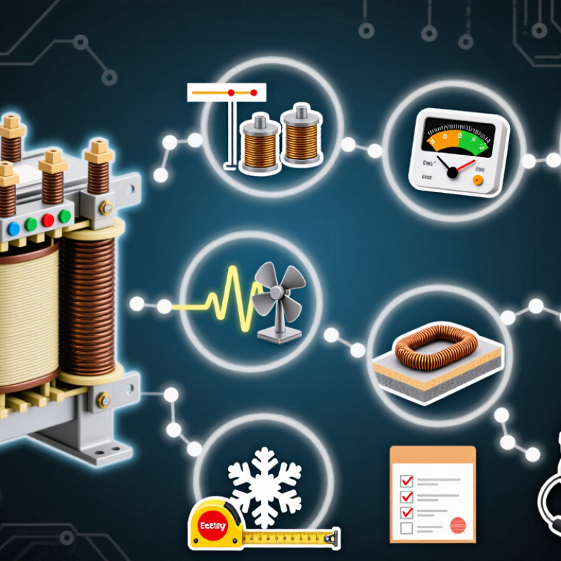
Define Operating Duty: 1 A/5 A Secondary, 50/60 Hz, Burden in VA
Define Operating Duty: 1 A/5 A Secondary, 50/60 Hz, Burden in VA
Selecting a high current transformer starts with the operating duty, not the headline current. Specify whether the secondary is 1 A or 5 A. At the same impedance, a 5 A circuit produces 25 times the copper loss of a 1 A circuit. Long control cables can therefore consume significant burden capacity. I have seen designs pass bench tests but fail after field wiring was added.
Burden must be stated in VA at the rated secondary current. For example, 5 VA at 5 A equals 0.2 ohms total impedance, including meters, relays, terminals, and cables. The same 5 VA at 1 A allows 5 ohms. This difference affects voltage drop, heating, and measurement accuracy. IEC 61869-2 and IEEE C57.13 both require attention to rated burden and accuracy performance. Do not treat VA as a decorative specification.
Frequency matters too. A transformer designed for 50 Hz may not deliver identical saturation margin at 60 Hz under every waveform. Confirm continuous, intermittent, and overload duty separately. The U.S. Department of Energy has estimated that distribution transformers consume roughly 2%–3% of national electricity use, showing why small efficiency losses deserve attention. The IEA Electricity 2024 report also projects strong electricity-demand growth through 2026. More loading is coming. A neat spreadsheet can still mislead when harmonics, ambient temperature, or cable length are missing. Verify them.
Choosing the Right High Current Transformer: Burden Voltage at 1 A and 5 A Secondary Ratings
Burden voltage is calculated as V = VA ÷ A. For the same VA burden, a 1 A secondary produces five times more voltage than a 5 A secondary. Confirm the transformer's rated secondary current, 50/60 Hz operating frequency, and total connected burden before selection. The total burden should remain within the transformer's rated VA capacity.
Prevent Saturation: Knee-Point Voltage, ALF 5–20, and Excitation Current
A high-current transformer can look oversized and still saturate during a fault. The critical checks are knee-point voltage, accuracy limit factor, and excitation current. These values show how well the core handles rising secondary voltage.
Knee-point voltage
Knee-point voltage marks the region where a small voltage increase causes a sharp excitation-current rise. Select a protection transformer with sufficient margin above the calculated burden voltage. Include winding resistance, cable resistance, relay impedance, and connection points.
A practical field check is simple: raise the secondary voltage slowly and record the excitation current. Watch the curve, not only the catalog value.
Accuracy limit factor, or ALF
Accuracy limit factor, or ALF, commonly ranges from 5 to 20. An ALF of 10 means the transformer should maintain its specified accuracy up to ten times rated secondary current, under the stated burden. That promise depends on real wiring. Long cables can quietly consume the margin. They are easy to underestimate.
Excitation current
Excitation current should remain low before the knee point. A sudden rise signals approaching saturation. Test results may differ from calculations. That is normal. Temperature, residual magnetism, and measurement wiring can influence the curve.
One overlooked detail can distort the decision. Review the test setup before rejecting the transformer. When available fault current is high, compare the expected secondary voltage directly with the measured knee-point value, rather than trusting ALF alone.
Verify Fault Withstand: IEC 61869-2 Idyn = 2.5 × Ith
Choosing a high current transformer requires more than matching the normal load current. Fault withstand deserves careful attention, especially in compact switchgear with limited space. Under IEC 61869-2, the rated dynamic current, Idyn, is typically 2.5 times the rated short-time thermal current, Ith. This relationship reflects the mechanical stress created by the first peak of a short-circuit current.
Check the fault study, not only the equipment nameplate. If the calculated three-phase fault current is 31.5 kA for one second, the transformer’s Ith should meet or exceed that thermal duty. Its Idyn should also withstand the expected peak current. For example, an Ith rating of 31.5 kA implies an Idyn rating of 78.75 kA when the 2.5 ratio applies. Inspect the declared test values and duration carefully. They must match the project conditions.
Look closely at the installation.
Busbar spacing, conductor bracing, and mounting hardware can increase mechanical forces during a fault. A transformer may satisfy a catalog value yet remain unsuitable for its actual enclosure. That mistake is easy to make. I would also review asymmetrical fault currents, since the first peak may not resemble a clean sine wave. Site calculations are sometimes incomplete, and that deserves honest review. Ask for verified test data, clear certificates, and traceable technical records before approving the selection.

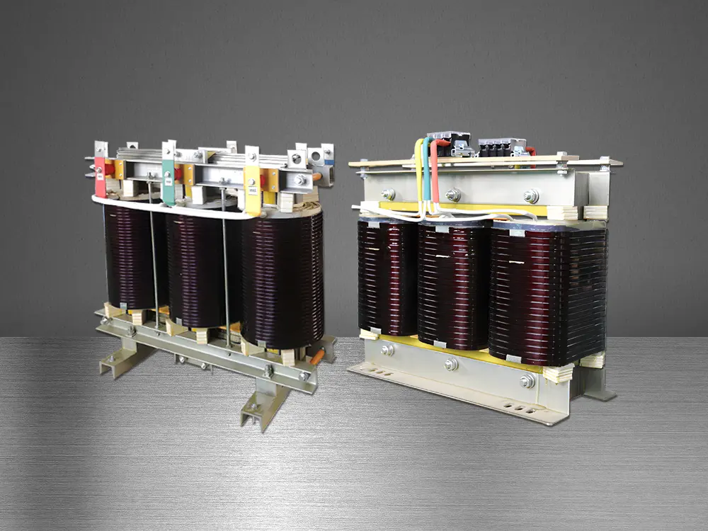 Three-Phase Isolation Transformer
 Control Transformer
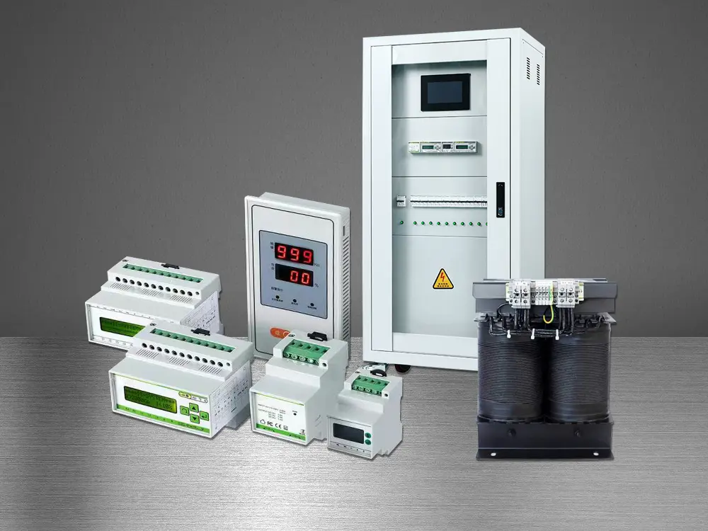 Medical IT Isolated Power System
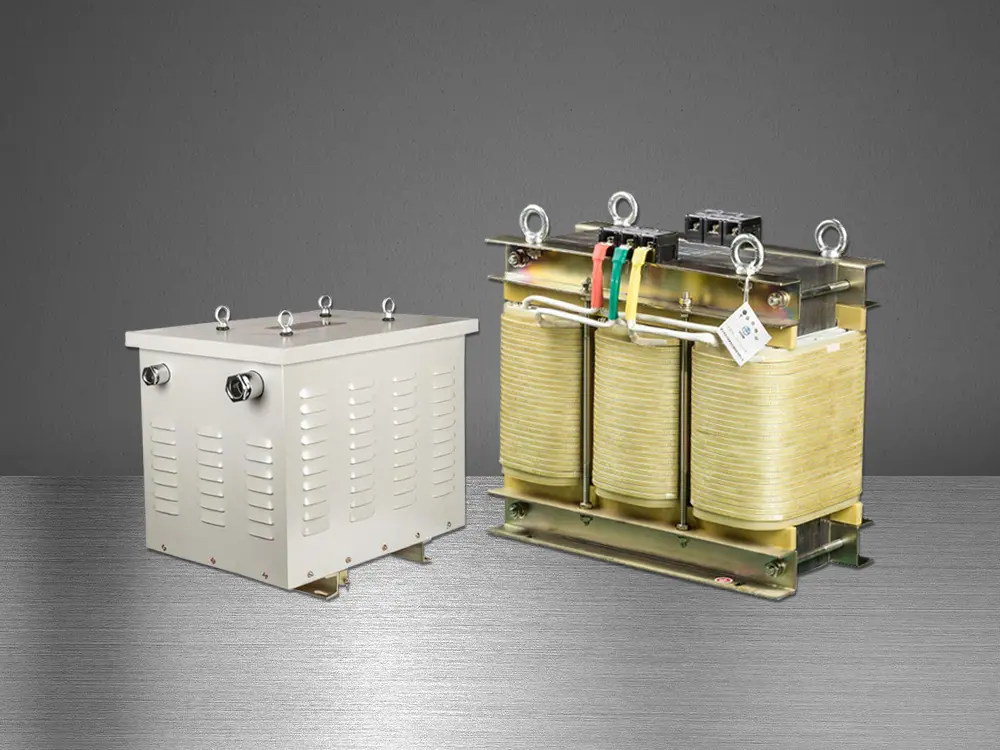 Marine Transformer
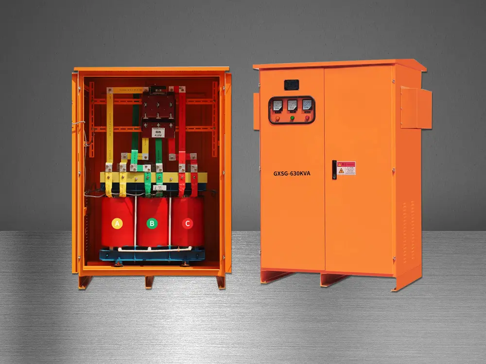 Tunnel Transformer
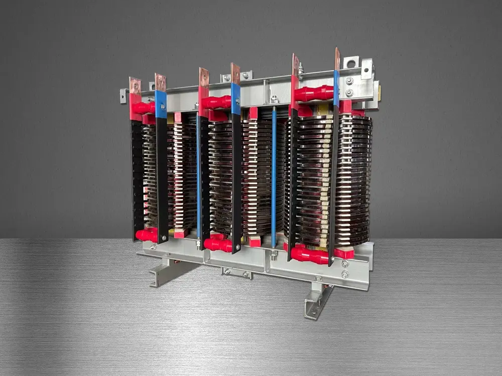 High Current Transformer
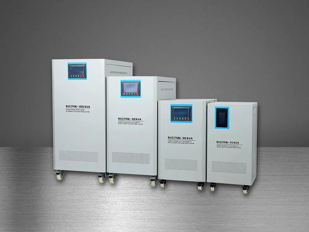 Automatic Voltage Regulator
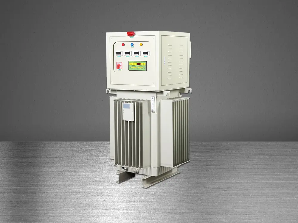 Oil Immersed Voltage Regulator