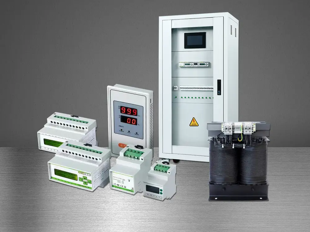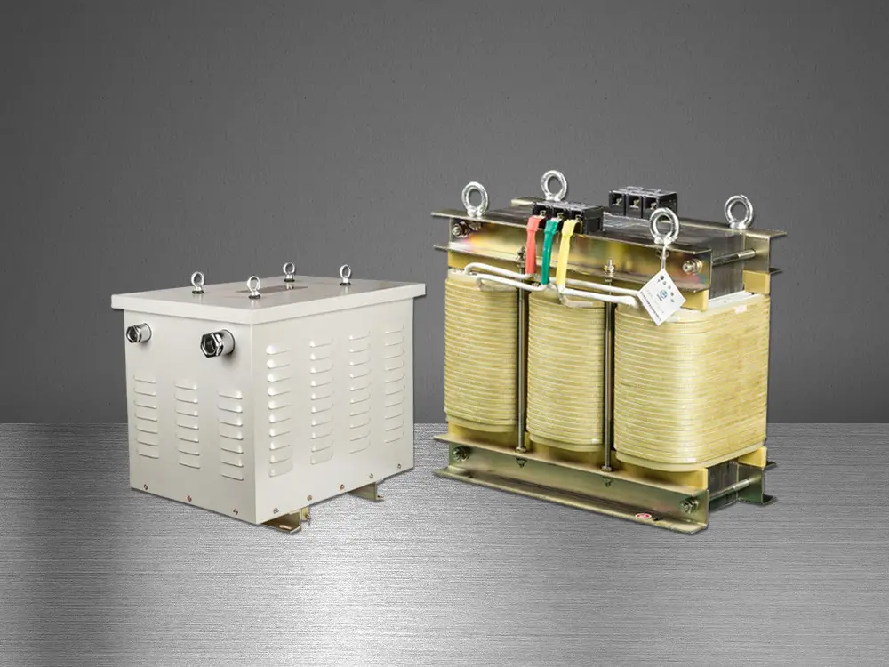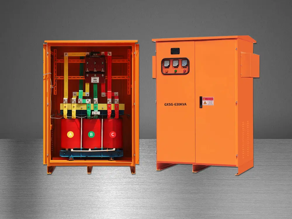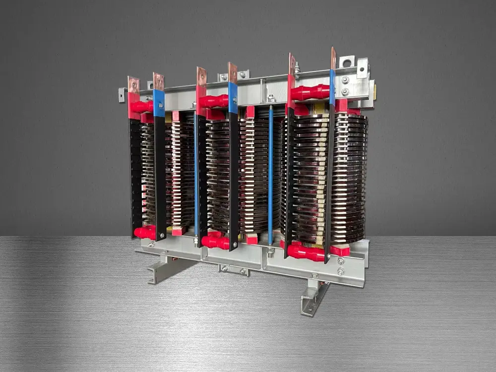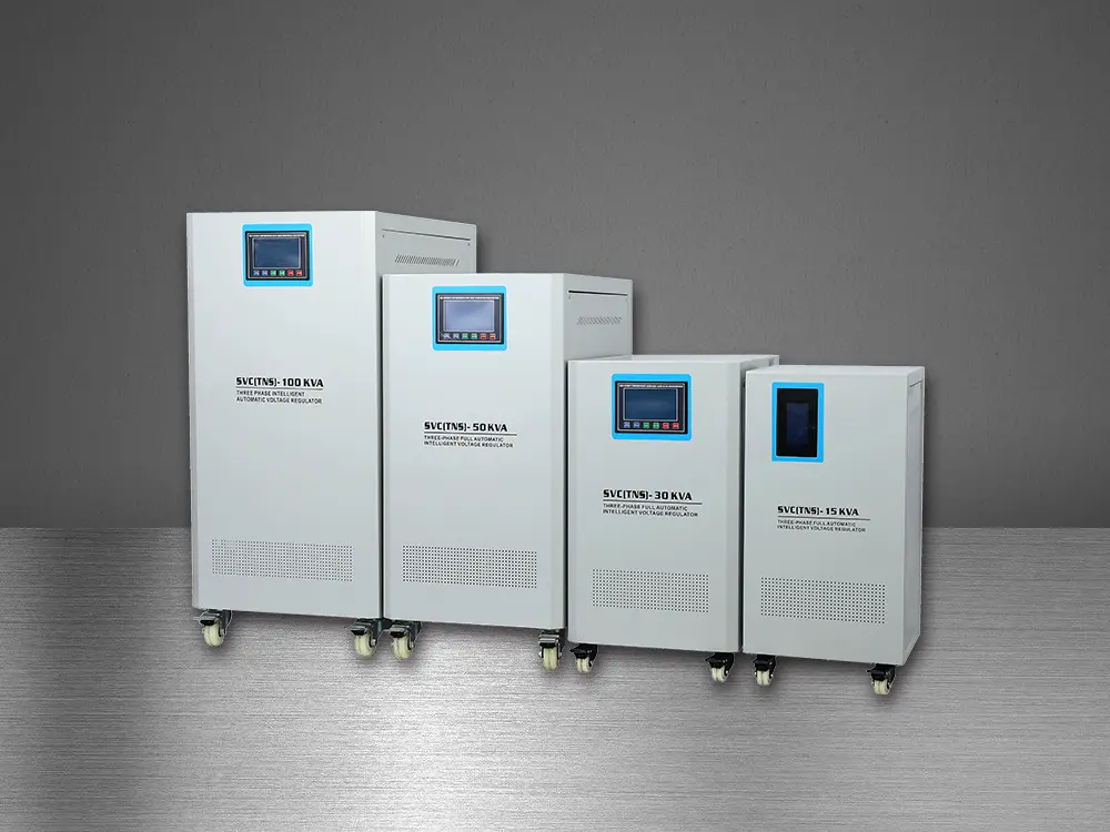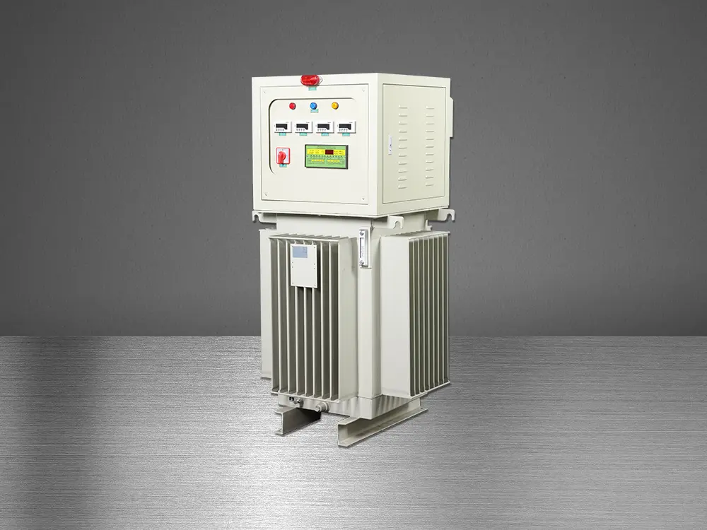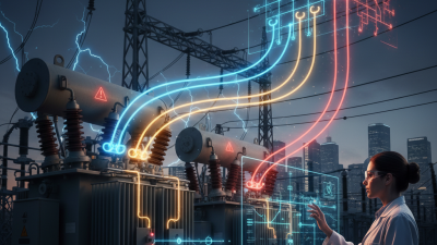
A High Current Transformer is designed for one demanding task: moving electrical energy while carrying unusually large current. Its magnetic core transfers energy between windings without direct electrical contact. The primary winding receives power. The secondary winding delivers a changed voltage and current.
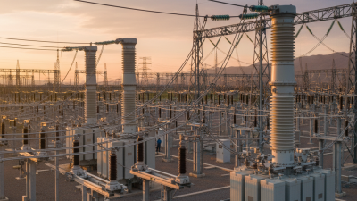
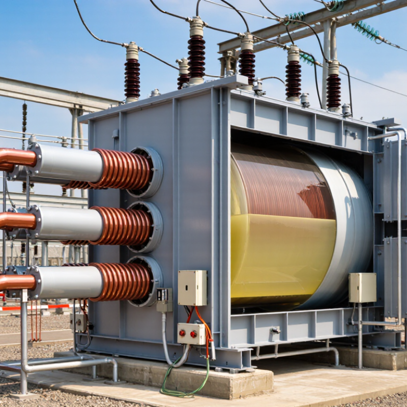
The scale becomes tangible in a substation. Thick copper conductors enter the tank, cooling oil circulates around the windings, and protective relays watch for heat or insulation failure. The transformer may operate continuously, not occasionally. That makes thermal design, short-circuit strength, and maintenance central to its reliability. Small design errors can become expensive outages.
The International Energy Agency’s Electricity 2024 report expects global electricity demand to grow strongly through 2026. This growth increases pressure on transmission and distribution equipment. The U.S. Department of Energy has also identified transformer supply, aging infrastructure, and material availability as important grid concerns. These reports do not describe every High Current Transformer application. However, they show why capacity and resilience matter.
Transformer engineer James H. Harlow has described transformers as “the backbone of the electric power system.” The phrase is simple. The engineering is not.
This guide explains magnetic induction, current ratios, cooling systems, and protection methods. It also examines where specifications can mislead. A higher current rating does not automatically mean better performance. Efficiency, impedance, harmonics, ambient temperature, and fault conditions must be considered together. Real installations are less tidy than textbook diagrams. That is worth remembering.
A high current transformer is an electrical device designed to transfer power while handling unusually large current levels.
Its core purpose is controlled energy conversion, not simply producing more electricity.
In many applications, it reduces voltage so the secondary winding can deliver high current safely.
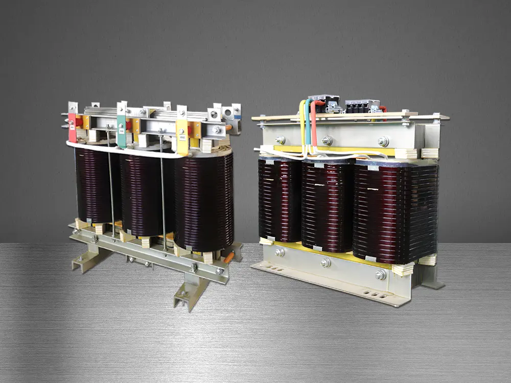
Thick copper conductors, a magnetic steel core, and strong insulation support this demanding work.
When alternating current enters the primary winding, it creates a changing magnetic field in the core. That field induces voltage in the secondary winding.
The turns ratio determines the voltage and current relationship. Fewer secondary turns usually produce lower voltage and higher current.
This output can support welding equipment, industrial heating, battery systems, and heavy machinery.
In field inspections, warm terminals, darkened insulation, or unusual humming can reveal poor connections or excessive loading.
The label alone is not enough; actual measurements matter.
Tips: Check the rated current, voltage, frequency, and duty cycle before installation.
Use a suitable protective device and verify that connections are tight. Keep cooling paths clear, especially around enclosed units.
A temperature check after startup can expose problems early.
I have found that many failures begin with small installation errors, not dramatic electrical events.
However, temperature readings can vary with load and environment, so one measurement should not decide everything. Always follow qualified engineering procedures and the applicable electrical safety requirements.
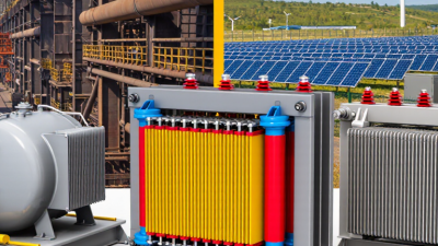
A high-current transformer is usually a current transformer (CT). It converts heavy primary current into a smaller, measurable secondary current. The primary may be a copper busbar passing through the core. The secondary commonly delivers 1 A or 5 A to meters and protection relays. The magnetic core concentrates flux and determines accuracy, saturation behavior, and fault response. Copper windings carry the transformed current. Insulation separates conductors from each other and the grounded enclosure. Terminals connect the CT to instruments, while the enclosure controls clearance, heat, and moisture. Simple parts.
The design choices matter under real network stress. The IEA Electricity 2024 report expects global electricity demand to add more than 2,500 TWh from 2024 through 2026. The U.S. Department of Energy’s 2024 transformer supply-chain review projects distribution-transformer demand may increase 160% to 260% by 2050, depending on electrification. This growth pressures cores, copper, insulation, and testing capacity. Engineers specify ratio, accuracy class, burden, short-circuit withstand, and thermal limits together.
A saturated core can distort readings during a fault. That is not a minor error. It can delay protective action. Never open-circuit an energized CT secondary. Dangerous voltage may develop.
Field temperature, cable length, grounding, and relay resistance can also change performance. Experienced teams still miss details. Commissioning tests and independent review remain valuable.
A high-current transformer transfers electrical current through magnetic induction, not direct electrical contact. An alternating current in the primary winding creates changing magnetic flux inside a laminated iron or magnetic core. That flux crosses the core and induces voltage in the secondary winding. The turns ratio controls the result: fewer secondary turns usually produce lower voltage and higher current. Simple physics.
For example, a 100:1 ratio could theoretically convert 10,000 volts and 100 amperes into 100 volts and 10,000 amperes. Real systems are less neat. Copper resistance, leakage reactance, core losses, and heat reduce the output. Engineers use wide copper bars, short current paths, thermal insulation, and cooling channels. In a current transformer, one busbar may act as the primary winding. Its multi-turn secondary commonly supplies 1 or 5 amperes to meters or protection relays. The secondary must never remain open while energized. Dangerous voltage can appear.
IEC 61869-2 specifies accuracy and protection requirements for current transformers. The International Energy Agency’s 2023 Electricity Grids and Secure Energy Transitions report projects annual grid investment above 600 billion dollars by 2030, nearly twice today’s level. More substations and industrial electrification will increase demand for compact, high-current equipment. Yet datasheet ratings can mislead when harmonics, ambient heat, or loose joints are ignored. Field measurements matter. A transformer may meet its ratio on paper, while its terminals still run dangerously hot.
A high-current transformer changes voltage while carrying substantial current through carefully designed windings. Its core guides magnetic flux, while copper or aluminum conductors transfer power with controlled losses. Safety starts with thermal management. Larger conductors reduce resistance, but parallel conductors can create uneven current sharing. Engineers therefore control lead length, connection geometry, and leakage reactance. Small details matter.
Cooling also determines safe continuous operation. Oil, air, or forced ventilation must remove heat from windings and joints. Temperature sensors should monitor the hottest practical points, not only the enclosure. IEC 60076 guidance addresses transformer ratings, insulation, and short-circuit performance. In practice, commissioning teams should verify these limits under real load profiles. A nameplate rating can mislead. The U.S. Department of Energy’s 2024 distribution-transformer rule projects 3.6 quadrillion British thermal units in energy savings over thirty years, showing why loss reduction deserves serious attention. Efficient cores reduce no-load losses, while optimized conductors reduce load losses. Protection requires grounding, correctly rated fuses or breakers, and adequate clearances around energized parts. Short-circuit forces can deform windings within milliseconds. Mechanical bracing must resist them repeatedly, although designs are not always tested under every realistic fault pattern. That gap deserves review.
| Design Parameter | Typical Value or Configuration | How It Works | Contribution to Safe and Efficient Operation |
|---|---|---|---|
| Primary Current Rating | Hundreds to several thousand amperes, depending on the application | The primary winding or conductor carries the high-load current and produces the magnetic field required for energy transfer. | The rating must match the continuous and short-duration load profile to prevent overheating, excessive voltage drop, and insulation damage. |
| Secondary Current Rating | Commonly 1 A or 5 A for measurement and protection circuits | The transformer converts the high primary current into a lower proportional current that can be safely connected to meters, relays, and monitoring equipment. | Reduced secondary current improves personnel safety and allows standard protection and measurement devices to be used. |
| Current Transformation Ratio | Examples include 1000:5, 2000:5, or 4000:1 | The ratio is determined by the relationship between primary and secondary ampere-turns. The secondary current is proportional to the primary current within the specified accuracy range. | A correctly selected ratio prevents measurement saturation and provides reliable readings during normal operation and fault conditions. |
| Magnetic Core Material | Grain-oriented electrical steel, nickel alloy, or nanocrystalline material | The core concentrates magnetic flux around the windings and improves electromagnetic coupling between the primary and secondary circuits. | Low core loss reduces heat generation, while suitable magnetic properties help maintain accuracy and delay saturation. |
| Core Cross-Section | Sized according to volt-ampere burden, frequency, flux density, and fault requirements | A larger or properly optimized core carries the required magnetic flux without reaching its saturation limit. | Adequate core sizing reduces waveform distortion, protects connected relays, and improves performance during high-current faults. |
| Primary Conductor Arrangement | Bar primary, wound primary, or window-type design | The primary conductor may pass through the core once or form several turns, depending on the required current ratio and physical construction. | Bar and window designs can reduce resistance and simplify installation for very high currents, while proper conductor sizing limits thermal losses. |
| Secondary Winding | Fine insulated copper winding with a precisely controlled number of turns | The secondary winding generates a lower current through electromagnetic induction while maintaining a defined relationship with the primary current. | Accurate winding placement and insulation help reduce ratio error, phase error, dielectric stress, and the risk of internal faults. |
| Rated Frequency | Typically 50 Hz or 60 Hz in power-system applications | The alternating primary current creates a changing magnetic flux, which induces voltage and current in the secondary winding. | Operating at the rated frequency prevents excessive core flux, overheating, and avoidable accuracy errors. |
| Accuracy Class | Measurement classes such as 0.1, 0.2, 0.5, or 1.0; protection classes are specified separately | The accuracy class defines the allowable ratio and phase errors under stated operating conditions and burden limits. | Choosing the correct class ensures dependable energy measurement or protective relay operation without unnecessary cost or oversizing. |
| Rated Burden | Specified in volt-amperes, commonly from a few VA to several tens of VA | Burden is the total load connected to the secondary, including cable resistance, meters, and protective relays. | Keeping the actual burden within the rated value maintains accuracy and prevents the secondary voltage from rising excessively. |
| Insulation System | Enamel, paper, polymer film, resin, oil, or molded insulation, selected for the voltage level | Insulation separates conductive parts and withstands normal operating voltage, transient stress, and environmental conditions. | Proper insulation coordination reduces partial discharge, flashover, moisture-related deterioration, and electric-shock hazards. |
| Thermal Management | Natural air cooling, forced air cooling, or liquid cooling for higher losses and larger assemblies | Heat generated by winding resistance and core loss is transferred to the surrounding air or cooling medium. | Maintaining the winding and insulation within their allowable temperature limits extends service life and reduces thermal failure risk. |
| Short-Circuit Withstand | Designed for specified short-time thermal and mechanical fault stresses | During a fault, high electromagnetic forces act on the windings and supporting structures while current produces rapid heating. | Strong bracing, secure winding support, and adequate conductor sizing help prevent deformation, insulation damage, and permanent loss of accuracy. |
| Secondary Terminal Safety | Dedicated terminals with shorting links or a short-circuiting block | When the primary is energized, the secondary must remain connected to its burden or be deliberately short-circuited. | An open-circuited current-transformer secondary can develop dangerously high voltage; shorting provisions reduce shock, arcing, and insulation risks. |
| Grounding Arrangement | One secondary point normally grounded in accordance with the protection and installation design | Grounding establishes a controlled reference potential and provides a path for fault current under abnormal conditions. | Correct grounding limits touch voltage and helps protective devices operate as intended. Multiple unintended ground points should be avoided. |
| Enclosure and Environmental Protection | Indoor or outdoor housing selected for dust, moisture, corrosion, temperature, and mechanical exposure | The enclosure shields the magnetic assembly, insulation, and terminals from contaminants and external damage. | Environmental protection reduces tracking, corrosion, insulation aging, and maintenance requirements. |
| Power Loss and Efficiency | Determined by winding resistance, core loss, operating current, frequency, and load burden | Losses appear mainly as copper loss in the windings and hysteresis and eddy-current losses in the core. | Low-resistance conductors, optimized core materials, and correct loading reduce energy waste and operating temperature. |
| Testing and Maintenance | Ratio, polarity, insulation resistance, winding resistance, burden, and protection-performance tests | Electrical tests verify that the transformer continues to meet its specified performance and insulation requirements. | Periodic inspection can identify loose connections, overheating, insulation deterioration, and accuracy changes before they cause an outage. |
Note: Actual ratings and construction details depend on the application, system voltage, frequency, installation environment, accuracy requirements, and applicable electrical standards.
A high current transformer transfers electrical energy while delivering unusually large current at a controlled voltage. Its primary winding receives input power, and electromagnetic induction creates voltage in the secondary winding. Fewer secondary turns usually produce lower voltage and higher current. The iron core guides magnetic flux between both windings. This sounds simple, but physical design becomes demanding at high current levels.
Common applications include industrial power supplies, welding equipment, electrolysis systems, battery charging stations, and renewable energy converters. These systems often need stable current for long operating periods. A transformer used in welding may tolerate short, intense current pulses.
A battery charger usually requires smoother output and tighter voltage control. High-current distribution systems may use copper bars instead of thin wires. They reduce resistance and help manage heat.
Performance depends on more than the rated current. Copper loss can raise winding temperature, while core loss increases with frequency and magnetic flux. Engineers should check cooling airflow, insulation strength, duty cycle, leakage inductance, and short-circuit behavior. Poor ventilation can shorten service life quickly. Very high current also creates strong mechanical forces during faults. Secure connections are essential. Measurement equipment must match the expected current and insulation level. In practice, calculations rarely tell the whole story; temperature testing under realistic loads can reveal weaknesses. I have found that a slightly oversized transformer often performs more reliably, although it may increase cost, weight, and installation space.