Leave Your Message

How to Choose a Marine Isolation Transformer in 2026?

Choosing a Marine Isolation Transformer in 2026 is not just a matter of matching a number on a label. The right unit should suit the vessel’s shore-power supply, onboard voltage, frequency, and expected electrical load. Start with the equipment you actually use: a battery charger, air conditioner, galley appliances, and other simultaneous loads can quickly change the capacity required. Allow for startup surges, too. Motors may demand more power briefly than their running figures suggest.

Physical conditions matter. Check available installation space, ventilation, cable access, weight, and the manufacturer’s environmental ratings. A cramped locker or damp engine-room corner can turn a suitable transformer into a poor choice. Look for clear specifications, wiring diagrams, protection guidance, and accessible technical support from the manufacturer. Confirm compatibility with the vessel’s existing electrical system before purchase.

A properly selected transformer can provide galvanic isolation between shore power and the boat’s electrical system, helping reduce certain corrosion risks. It does not replace sound bonding, grounding, overcurrent protection, or careful installation. That distinction is easy to overlook. Consult a qualified marine electrician when assessing the system, especially if its wiring history is unclear. Even experienced owners can miss a load or installation constraint; checking assumptions is part of making a reliable choice. This guide explains the practical questions to ask before comparing models, so the final selection reflects real operating conditions—not just a tempting price or an oversized specification.
How to Choose a Marine Isolation Transformer in 2026?

Understanding the Role of a Marine Isolation Transformer

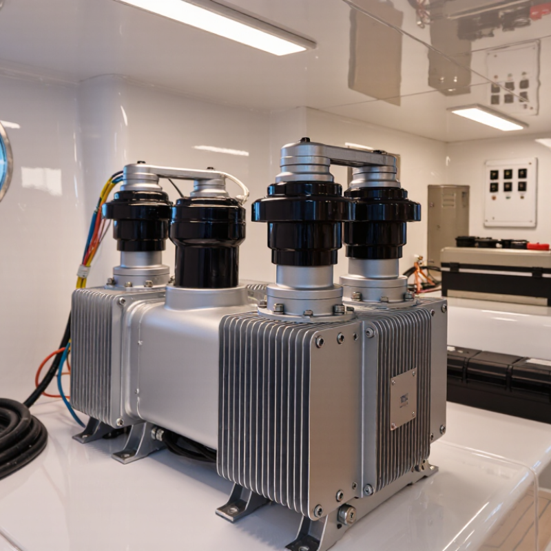
A marine isolation transformer sits between shore power and a vessel’s electrical system. Its windings transfer energy magnetically, with no direct conductive connection between the two circuits. This separation can interrupt some galvanic-current paths through shore-power grounding connections, helping reduce corrosion on underwater metals. It may also limit certain electrical disturbances passed from the dock. Not by itself.

The transformer does not replace the vessel’s protective-earth system or correct faulty wiring. Its enclosure, bonding, and overcurrent protection must suit the installation. A qualified marine electrician can check how it integrates with the boat’s grounding arrangement. Details matter. An incorrectly installed unit can create new hazards instead of improving safety.

When choosing one in 2026, match its continuous power rating to the vessel’s real loads, including equipment startup surges. Check input and output voltage, frequency, cooling needs, weight, and resistance to vibration and moisture. A rating on paper can hide practical limits: a unit tucked into a hot, cramped locker may not perform like one with adequate airflow. I would not select by kilovolt-amperes alone; the vessel’s layout and shore-power conditions deserve a careful look.

How to Choose a Marine Isolation Transformer in 2026?

Example Output Current from a 5 kVA Single-Phase Transformer

A marine isolation transformer separates the vessel’s AC system from shore power, helping reduce the risk of galvanic corrosion and providing electrical isolation. This chart shows the ideal current available from a 5 kVA transformer at common single-phase voltages, calculated as current = apparent power ÷ voltage. Choose a transformer based on your vessel’s supply voltage, frequency, continuous load, and manufacturer ratings; actual usable current may be lower.

Assessing Vessel Power Needs and Shore Supply Conditions

Before selecting a marine isolation transformer, list the vessel’s actual loads: air conditioning, galley equipment, battery chargers, pumps, and motor-starting demand. Check the nameplates for voltage, phase, frequency, and current. Then compare them with the shore pedestal’s measured supply, not just its label. A transformer can adapt voltage and provide galvanic isolation; it does not convert 50 Hz power to 60 Hz. That mismatch needs separate attention.

Shore conditions vary by marina and berth. Confirm the available amperage, wiring condition, protective devices, and grounding arrangement with a qualified marine electrician. The European Maritime Safety Agency’s 2024 European Maritime Transport Environmental Report estimates that maritime transport produces about 3–4% of the EU’s total CO2 emissions. Shore-side power can help reduce emissions while vessels are alongside, but only when the vessel and supply are compatible. Standards such as IEC 60092-507 provide useful guidance for small-vessel electrical installations. A neat calculation can still miss real-world starting surges.

Tips: Record voltage and frequency at the dock under load, then compare them with the vessel’s equipment ratings. Include simultaneous use and motor-starting current in the load estimate. Keep the readings; memory is unreliable.

How to Choose a Marine Isolation Transformer in 2026? — Assessing Vessel Power Needs and Shore Supply Conditions

Use these example load profiles and checks as an initial screening guide. Final sizing must account for the vessel’s actual load schedule, installation conditions, and applicable marine electrical requirements.

Assessment area Vessel or shore-supply condition Example data or calculation Selection implication
Example vessel load profiles
Small auxiliary loads Refrigeration, battery charging, lighting, and general outlets; estimated maximum simultaneous load of 6 kW at 0.85 power factor. 6 kW ÷ 0.85 = approximately 7.1 kVA. A 10 kVA unit may be a preliminary candidate if starting loads and future additions are covered. Check compressor and charger inrush currents. Confirm that the shore connection can supply the required input current.
Typical mid-size vessel loads Several hotel loads and equipment circuits; estimated maximum simultaneous load of 15 kW at 0.90 power factor. 15 kW ÷ 0.90 = approximately 16.7 kVA. A 25 kVA unit may provide a practical screening margin, subject to the load study. Review how often large loads operate together, including air-conditioning, cooking equipment, and battery charging.
Higher continuous demand Estimated maximum simultaneous load of 30 kW at 0.90 power factor. 30 kW ÷ 0.90 = approximately 33.3 kVA. A 45 kVA unit may be considered for preliminary evaluation. Verify continuous-duty rating, ventilation, temperature derating, harmonics, and the available shore-service capacity.
Large hotel or service load Estimated maximum simultaneous load of 60 kW at 0.90 power factor. 60 kW ÷ 0.90 = approximately 66.7 kVA. A 75 kVA or larger rating may be evaluated after a detailed load and starting-current study. Confirm that the dock supply, cable, connector, and protective devices can support the required power.
Shore supply and electrical compatibility
Single-phase shore connection 230 V, 32 A single phase. Apparent power is approximately 230 V × 32 A = 7.4 kVA. A transformer cannot increase the power available from the dock. Allow for losses and avoid planning vessel loads above the shore limit.
Three-phase shore connection 400 V, 32 A, three phase. Apparent power is approximately √3 × 400 V × 32 A = 22.2 kVA. Confirm the shore connection’s phase count, voltage, frequency, current limit, and the vessel’s required output configuration.
Voltage ratio Shore voltage differs from the vessel’s required distribution voltage. Specify the required primary and secondary voltages, phase arrangement, and any permitted voltage tolerance. An isolation transformer may be designed with a voltage ratio, but verify the actual connection and output under load.
Frequency Shore supply is 50 Hz or 60 Hz; vessel equipment may be frequency-sensitive. Check the frequency rating of the transformer and every connected load. A standard transformer does not convert frequency. Use suitable frequency-conversion equipment if the vessel requires a different frequency.
Starting and transient loads Motors, compressors, pumps, and some power-electronic equipment have brief high starting or inrush currents. Compare equipment starting-current data with transformer impedance, upstream protection, and shore-service limits. Do not size solely from average running watts. Confirm the transformer can support the expected starts without excessive voltage drop or nuisance trips.
Non-linear loads Battery chargers, inverters, and variable-speed drives may draw distorted current. Obtain harmonic or total harmonic distortion data when available. Check the transformer’s suitability for the load profile and any required thermal derating.
Installation and protection checks
Electrical isolation and bonding Shore power is connected to a vessel’s onboard distribution system. Review the transformer’s isolation arrangement, secondary neutral and bonding scheme, and protective-earth connections. Have a qualified marine electrical professional verify the complete grounding and fault-protection design for the vessel and local rules.
Corrosion protection Vessel is connected to shore power for extended periods in a corrosive marine environment. Assess the vessel’s galvanic-corrosion protection arrangement and any existing galvanic isolator. Confirm that the isolation transformer is installed and bonded as intended; do not assume that all products or wiring arrangements provide the same protection.
Physical installation Limited machinery-space access, vibration, heat, moisture, or restricted airflow. Check enclosure protection, mounting, clearance, ventilation, ambient-temperature rating, weight, and service access. Choose equipment suitable for the actual installation location and follow its installation instructions.
Final rating decision Load estimates, shore limits, voltage, phase, frequency, and installation details have been collected. Compare continuous kVA demand with the available shore capacity, then verify inrush, derating, protection, and expected future loads. Confirm the final rating and wiring design with a qualified marine electrician and applicable regulations before installation.

Screening formulas: Single-phase apparent power (kVA) ≈ voltage (V) × current (A) ÷ 1,000. Three-phase apparent power (kVA) ≈ √3 × line voltage (V) × line current (A) ÷ 1,000. Approximate transformer kVA for a load may be estimated as real power (kW) ÷ power factor. These calculations do not replace a load study or equipment-manufacturer data.

Selecting Transformer Capacity, Voltage, and Frequency

For a marine isolation transformer, size capacity from the loads it will actually serve—not the vessel’s total nameplate load. Add the continuous volt-ampere demand of connected equipment, then account for motor-starting current, simultaneous operation, and nonlinear loads such as variable-frequency drives. Check the transformer’s overload and temperature-rise ratings against the engine-room environment. A cold rating on paper may not reflect heat, vibration, or restricted ventilation in a real compartment. Allow room for measured load growth, but avoid oversizing blindly; a lightly loaded transformer can still bring unnecessary cost and space demands.

Match both primary and secondary voltage to the vessel’s measured supply and each load’s required input. Common shipboard examples include 440 V at 60 Hz and 400 V at 50 Hz, but these are not universal. IEC 60092-201:2019 addresses shipboard electrical-system design for 50 Hz and 60 Hz supplies; verify the actual equipment nameplates and system documents before specifying a unit. Frequency matters. A 50 Hz transformer connected to 60 Hz may operate differently, while voltage mismatch can cause overheating or poor performance. Confirm winding configuration, grounding, and available fault protection with a qualified marine electrical professional. This is where tidy spreadsheets can mislead. Real load measurements are better.

Comparing Isolation, Shielding, and Marine-Grade Protection Features

A marine isolation transformer separates shore-power conductors from the vessel’s AC system, helping limit galvanic-current paths through the water. A screened transformer adds an electrostatic shield between windings. That shield can reduce capacitive electrical noise, but it does not replace proper grounding, bonding, or overcurrent protection. Check the wiring diagram and ask whether the screen is connected as specified. Small detail. Often overlooked.

Marine protection deserves equal attention. IEC 60529 defines IPX7 as temporary immersion up to 1 metre for 30 minutes; that rating does not automatically establish resistance to salt corrosion. IEC 60068-2-52 describes cyclic salt-mist testing with eight severities, useful when comparing enclosure materials and coatings. Ask for the actual test level and installation conditions, not just “marine grade.” Also inspect terminals, cable entries, ventilation, and mounting hardware: salt deposits around a gland can undermine an otherwise robust enclosure. The trade-off is not tidy. A sealed unit may resist water better, yet still need adequate cooling and service access. Match protection claims to the vessel’s location, exposure, and shore-power arrangement.

Checking Standards, Installation Requirements, and Ongoing Maintenance

Choose a marine isolation transformer by matching its rating to the vessel’s supply voltage, frequency, and expected load. Check the applicable marine electrical standards, such as the relevant IEC 60092 requirements, along with classification-society and flag-state rules. Requirements can vary by vessel and installation. Verify the unit’s documentation before purchase.

Installation details matter. Mount the transformer securely on a dry, ventilated surface, with clearance for cooling and future inspection. Keep it away from bilge water, fuel lines, and excessive vibration. Follow the wiring diagram for primary and secondary connections, grounding, and bonding. Incorrect connections can defeat the intended isolation. Have a qualified marine electrician confirm the arrangement, especially when shore power and onboard generators use different configurations.

Maintenance should include checking for loose terminals, corrosion, damaged insulation, unusual heat, and changes in hum or vibration. Isolate power before inspection; electrical testing belongs to a qualified person using suitable procedures. Keep a log of temperatures, test results, and repairs. Small details matter. A checklist can still miss a slow change, such as salt residue forming beneath a cable gland, so inspect the surrounding area too.